Creating Custom Parts
First Things First
The first thing you'll want to do, is download and install the SDK.
Having done that, you should also download the personal version of Unity.
Now you can open up the Unity project included in the SDK. It contains a number of example parts for you to check out and see just how they're basically set up.
Creating Your Own New Part
Here we'll assume you already have some modelling tool, such as Blender and can use it enough to create the model for the part you're setting up.
Start by exporting your mesh. The .FBX format is recommended.
Drag and drop the exported file into the Unity project found in the SDK. You can position it next to the included example parts, so you get a sense of scale.
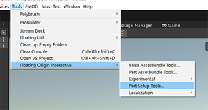
Now, Under the "Tools" menu, Navigate through "Floating Origin Interactive" and open up "Part Setup Tools..."
This handy little gadget can automate setting up your newly imported mesh and turn it into an almost ready-to-go addon part.
There are many tools available for your newly created part. Some are optional, depending on what kind of part you are setting up. But a few items do need to be added so that your part can work properly in the game.
Colliders
Part Colliders are just regular Unity Collider components. Add yours as an object under "model" in your part's object hierarchy. It should sit next to your mesh.
You may also use simpler shapes, like Box or Capsule, or even a combination of multiple of these. Just make sure they go under model.
Attachment Nodes
Most parts are intended to attach directly to the surface of others. For this, add a Surface Node by clicking the button for this purpose.
A new object appears under "model". This is the exact position by which your part will be dragged around when attaching to another. Adjust it's position as needed using the Unity gizmo.
You may skip this step if your part is not meant to attach directly to any surfaces. But you'll then want to add another type of attachment node.
For all nodes, the positional logic remains the same. Simply place it relative to your mesh wherever you wish the attachment point to be.
The Orientation of these nodes, however, is a bit more specific. A Surface Node should be rotated to match the normal (direction pointing straight out) from the part where yours is being attached. That means it should usually point it's Z axis towards your part.
Stack Nodes, however, need to be pointed outwards, facing the target connector in order for your part to attach in the proper direction against it.
Volumetrics
Kithack Model Club uses an intricate volumetrics system to determine how your vehicle behaves in water according to its shape. This requires it to know in advance the shape of all parts, so that they may be combined into a vehicle-wide voxel-grid representation of whatever you assemble.
All parts need to have their volumes defined for this. Click the "Setup part volume cfg" button on the Tools panel to add the necessary component.
Selecting "model" you should find "Part Volume Cfg" component on the inspector for this object. It looks complex, but do not despair, most of its functionality is automated.
With a previously made mesh under "model", installing this component should automatically assign its Mesh Filter as the source for the voxelizer. If it doesn't, drag the mesh from the hierarchy into the field next to "Mesh Filter" (or "Mesh Collider", should you prefer to have your collider represent the part's volume instead)
The voxelizer also needs a Transform to center the voxel grid around. This is usually the same as the part, and if not automatically setup, press "Fetch Mesh Transform" to use the mesh you just assigned as the coordinate frame for the volumetrics.
When done, hit :: Voxelize ::
You should see a grid of squares all over your part. That outlines the shape given by the system to your part in terms of voxels, within each, up to six surfaces may be found. Each surface has its own area and plane normal represented. Do not worry if the squares appear overly large or small, their display scale is only relative and can be adjusted by with the "Gizmo Normal Scale" and "Gizmo Fill CG Scale" fields. Set these as desired for best visualization.
Exporting Your Part
Make sure to set the Output Folder to the destination where the part files will be exported to. This may be your own Mod Folder, or a Parts subfolder inside it.
While it is possible to export directly to the game's Parts folder under Addons/Basegame, this is not recommended, as modifications done to basegame content will make your game fail CFG integrity checking, and you won't be able to play online in most servers.
When all is done, hit the green Export button on top of the part's main setup component. (the one where you give it it's name and description)
The process is fairly automatic, and will output the necessary files for your part to be loaded in the game.
Lastly, you should add the name of the part's output .cfg into the ModCFG File in your output folder. The game will not load your part if you do not do this.


